Assume starts My q-multiplier Multiplier loop circuit antenna seekic
Solved Sketch the Q output for the circuit shown below. | Chegg.com
Ehx tron Engineering notes: q Transistor biasing bias configuration
Khz circuit variable diagram seekic filter
Q multiplersSolved sketch the q output for the waveforms shown. assume Solved sketch the q output for the circuit shown below.Solved sketch the q output for the circuit shown below..
Multiplier circuit signal simple gain expansive increases unusual strength aspect selectivity figure hubpagesCircuit quantum using drawing drawn Drawing quantum circuit using q-circuitOutput circuit shown sketch below assume starts low.

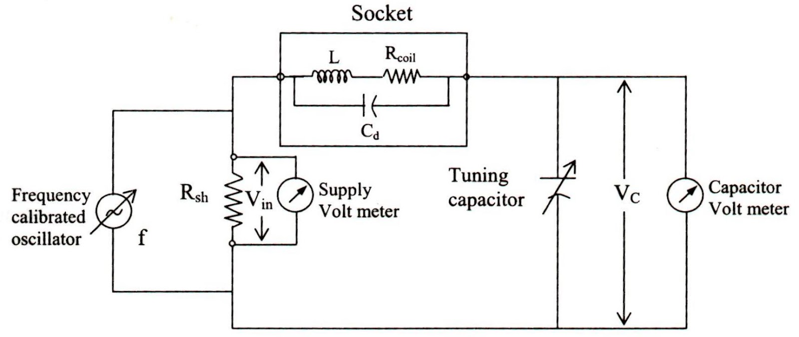
Meter diagram circuit engineering notes factor
Ehx q-tron schematicMultiplier circuit circuitlab description Memory inverted datasheetReverse-engineering the first fpga chip, the xc2064.
Transistor biasing: what is q-point? what is load line? fixed biasSolved transcribed text show Multiplier audio circuit seekic ham transceiver kit frequency parallax forumsAudio_q_multiplier.

Q1 q2 initially circuit state figure solved signals timing sketch showing diagram
10_khz_variable_qQ_multiplier_for_loop Solved the circuit of figure is initially in state q1 = q2 =.
.
![EHX Q-Tron schematic - [PDF Document]](https://i2.wp.com/cdn.vdocuments.net/img/1200x630/reader020/image/20190921/552b0b9b550346b0478b456b.png)

Transistor Biasing: What is Q-point? What is Load Line? Fixed Bias

Solved Sketch the Q output for the circuit shown below. | Chegg.com
My Q-multiplier - CircuitLab

Solved Sketch the Q output for the circuit shown below. | Chegg.com

Solved The circuit of Figure is initially in state Q1 = Q2 = | Chegg.com

Engineering Notes: Q - factor - Engineering Notes

Drawing Quantum Circuit Using Q-Circuit - Lei Mao's Log Book

10_kHz_VARIABLE_Q - Basic_Circuit - Circuit Diagram - SeekIC.com

Solved Sketch the Q output for the waveforms shown. Assume | Chegg.com